2. The
Baxandall Class-D Oscillator with a resonant trap
The
distortion in the sine wave output for lightly loaded inverters can be reduced
by putting a an extra LC filter in series with basic inductor LC to block the
second harmonic.
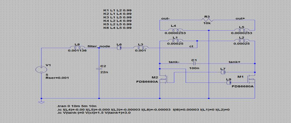
Adding the
inductor L8 and the capacitor C2 appreciably reduces the third harmonic spike
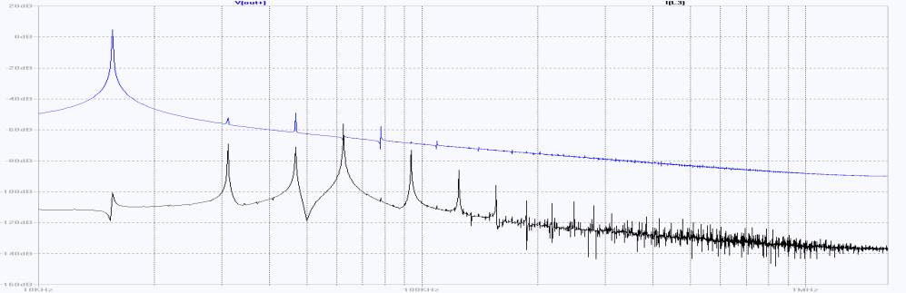
for a
lightly loaded tank circuit – there is now some second harmonic distortion, but
it is 56dB down on the fundamental, while the third harmonic component is also
55dB down, as opposed to 40dB down in the classic circuit.
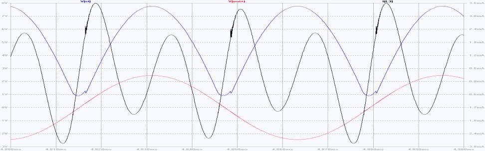
The current
swing in L3 is now reduced from around +/-17mA to around +/-3mA and the fourth
harmonic is now dominant.
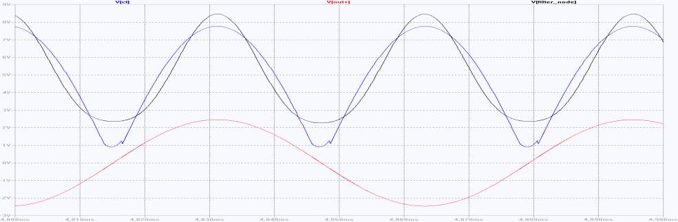
L3 no
longer sees all the voltage difference between the power supply and the centre
tap – the filter inductor L8 now deals with all most all the second harmonic
component, and the second harmonic current is now routed to ground through C2,
rather than being fed through the tank circuit. Comparing the voltage at the
“filter node” – the common point of L8, L3 and C2 – one can see how L3 has been
unloaded.
This isn’t
a particularly practical circuit. L8/C2 has to be tuned to be quite close to
the second harmonic of the tank circuit, and while we can buy 1% tolerance
capacitors in the values used in the examples, the sort of ungapped core
usually used the transformer/tank circuit (L1,L2,L4,L5) has a typical tolerance
around +/-25%. We could used gapped cores with adjustors, but this takes us a
long way away from the elegant simplicity of the original Baxandall circuit.